Printed Flexible Circuits Be Made
If you’re an engineer who is designing for flex circuits, there are some special things to consider. These include ensuring that the stackup can be reliably fabricated, making sure the flex circuits have tight bending radii and that they are surrounded by rigid-flex sections, and minimizing stress within the materials. You will also want to work with your preferred fabricator, and have them help you learn the nuances of a flex PCB design.
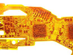
Flexible printed circuits (abbreviated FPC) have conductive traces on a thin, flexible substrate that can twist and bend. They can feature surface-mount devices like LEDs and resistors, and they often have a termination point or connector for integrating with other components. A flex circuit can also be embedded in a rigid dielectric stiffener material for additional strength and stability.
The main difference between a rigid PCB and a flex circuit is the fact that a flex circuit has a much thinner, flexible copper foil layer. This allows the traces to be bent and still maintain a high electrical conductivity. They also have a smaller overall footprint and can support higher densities of components. This makes them an excellent choice for applications that require a lot of wiring and are limited on space.
To make a flex circuit, copper is first laminated to a thin, non-conductive substrate such as polyimide or epoxy. Then, holes are drilled into each layer of the flex circuit using an automatic laser machine or by hand with a drill. A conductive pattern is then added to each of these layers by chemical baths and etching processes. Finally, the traces are soldered to the pads on both sides of the circuit board, and the resulting connections are tested with a flying probe machine.
How Thin Can Printed Flexible Circuits Be Made?
While there have been major advances in budget flex circuit manufacturing, it’s still rather expensive. One hobbyist, [Mikey77], is changing that by creating a flex circuit on his 3D printer.
He used AutoDesk 123D to create his flex PCB designs, and set each of them up so that the spacer bar sits at the bed level while the actual tracks are a few thousandths of an inch higher. This is enough to make the printed flexible circuits flex without destroying the track connections.
The resulting printed flexible circuits are very durable and have great flexibility, even at temperatures up to 150°C. They also offer better heat dissipation than traditional rigid PCBs, making them ideal for applications in harsh environments. In addition, they can reduce noise and improve signal timing for better reliability.
The key to making a successful flex circuit is the tight bending radius. The tighter the bending radius, the more stress that is placed on the copper and dielectric materials. The stress can cause work-hardening, fatigue fractures, and other failure modes, so designers must make sure the circuit’s flex radii are as small as possible to avoid damage. The best way to do this is by establishing pad and trace arrangement rules early on in the design process that use plating, anchoring stubs, and reduced coverlay access openings.